Configuration
This document describes the screens utilized to configure the Aspecto platform for operation.
Web Managment
This section describes the system requirements for using the web management interface. It also describes login and log out procedures, along with the application’s user interface.
Logging in to the Web Management Interface
The web management interface works with the latest version of Chrome, Firefox, and Safari.
To log in to the web management interface
-
Launch a supported Web browser.
-
In the browser address bar, type the URL on the serial number tag on the front of the box.
-
Press the Enter key. The following page appears:
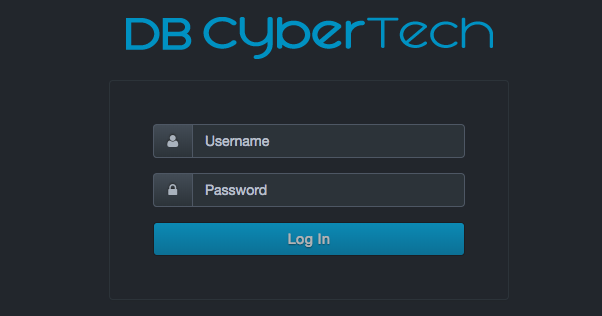
-
Each system is shipped with a unique 16-character password. Contact DB CyberTech Technical Support to obtain the administrative password assigned to your system.
-
Click Log In. The home page of the web management interface appears.
-
If this is the first time you are logging in, change the default password.
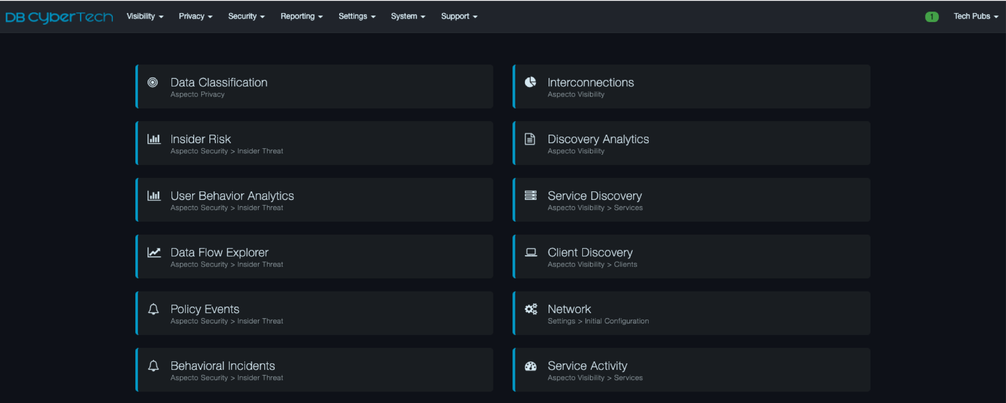
After logging in, the user will see the home screen:
Title Bar
The title bar appears at the top of the web management interface. The left side shows the unit name. You can change this name using Settings > Initial Configuration. The right side shows the current system date and time. A color-coded heart icon shows the health of the system:
-
Heart outline = the platform is unreachable temporarily.
-
Faded green heart = the platform is operational and idle.
-
Bright green heart = the platform is operational and busy.
-
Yellow triangle with exclamation point = the platform is not communicating. Either you have not logged in to the web management interface or the device is unreachable.
System Alert Indicator
A color-coded alert icon at the top-right side of the interface shows system alerts.

-
Green indicates an informational alert.
-
Orange indicates a warning.
-
Red indicates a critical alert that requires attention. If you receive a critical alert, contact DB CyberTech Technical Support.
If there is a combination of informational, warning, and critical alerts, the color defaults to the most severe alert.
A number inside the icon shows the total number of informational (green icon), warning (orange), or critical (red icon) alerts. In the following example, the system detected two critical alerts.
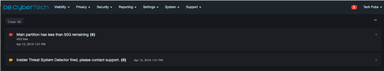
To view alert details, click the color-coded icon to open a panel containing information about the alerts. The following figure shows an example that displays all three types of alerts.
To clear individual alert messages, click the X at the top-right corner of the message. To clear all messages and close the panel, click Clear All at the top-left side of the panel and select Yes when prompted. To close the panel without clearing messages, click the up arrow at the top-right side of the panel.
 |
Note: Some critical alerts will recur, such as an alert about low remaining free space, until the alert has been resolved. |
Workspace
The workspace appears below the menu bar. When you click a menu option, the associated screen appears in the workspace.
When you log in to the web management interface or click
 in the header, the home page appears. This
page has quick-start buttons that allow you to access frequently
performed tasks without having to use the menus.
in the header, the home page appears. This
page has quick-start buttons that allow you to access frequently
performed tasks without having to use the menus.
Menu Bar
The menu bar appears at the top of the web management interface.
-
The left side shows the DB CyberTech logo and up to seven menus, depending on the features purchased and role assigned to the user. Clicking the logo returns you to the home page.
-
The right side contains the color-coded system alert indicator and the profile menu described above.

| | Note: The items shown on the home page may vary, depending on user permissions and the system’s current operating mode. |
Shared Interface Behaviors
Some pages in the web management interface share common behaviors. The buttons, icons, and drop-down lists associated with these common behaviors are located at the top of the workspace, as shown in the following figure. The following sections describe these shared behaviors.
Breadcrumbs
The web management interface uses “breadcrumbs” to indicate the path you have taken to arrive at the page displayed in the workspace. The breadcrumbs appear between the menu bar and the workspace. For example, if you click the Visibility menu, click Services, and then click Service Discovery in the left pane, the following breadcrumb appears.

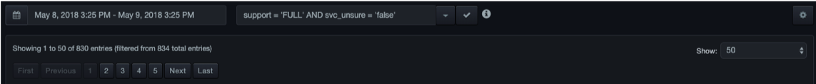
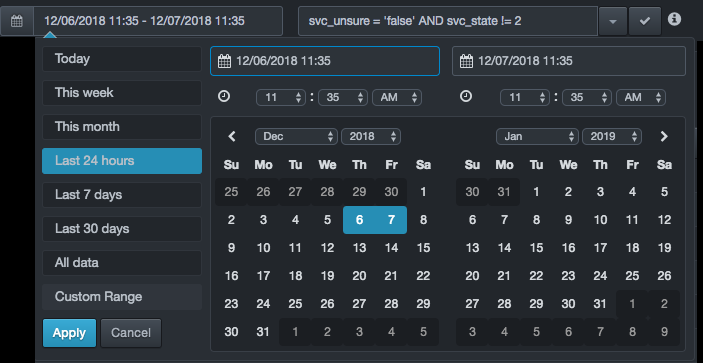
Selecting a Date Range
When the workspace contains a table of records, a field above the table allows you to specify a date range for the records shown.
When you click this field, a list of choices similar to the following appears.
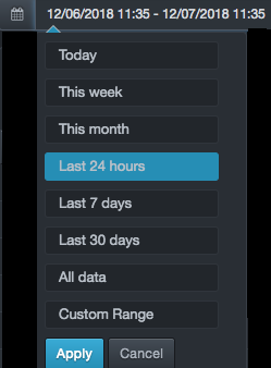
Click a predefined time or click Custom Range to select a date range from a popup calendar.
-
For predefined times (the first seven selections), the platform computes the current system time using the traffic feed time of the data stream. The feed time is the time that the last database traffic was observed and processed. Under normal operation, the current system time and feed time are the same. However, if the system is in File Playback mode, where older traffic might be replayed, the feed time and system time might be different.
-
If you click All data, there might be a delay, depending on the size of your environment and how long the system has been collecting information.
When you finish, click Apply.
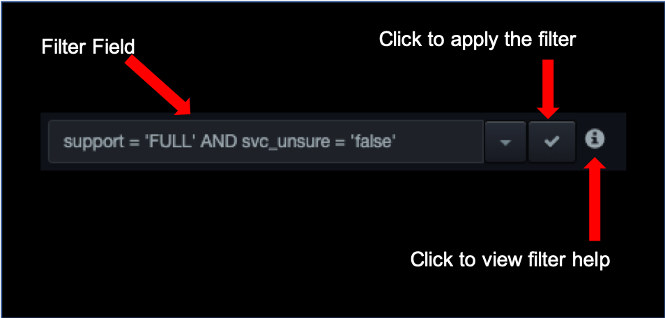
Filtering Records
When the workspace contains a table of records, a filter field above the table allows you to enter filter criteria that control the data shown in the table. Using this field, you can view only the records that interest you and hide the records that do not match the filter criteria.
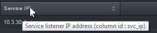
A filter consists of the column identifiers in the table, along with various conditions that records must match for them to appear in the table. To find the identifiers for the columns, hover your mouse over the column headers; the column identifier appears in parentheses, along with a complete list of column identifiers. The following figure shows how to find the ID for the Service IP column that appears in the Visibility > Service Activity page.
Filter conditions can be simple or complex, and can include the AND and
OR keywords to create filters that are broad or narrow as required. For
a complete description of filtering conditions, click the
 icon next to the filter field.
-
To filter records
-
In the filter field, enter the filter criteria.
-
Next to the filter field, click the
 icon.
The table shows only the records that meet the filter criteria.
icon.
The table shows only the records that meet the filter criteria.
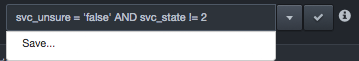
To save the filter for future use:
-
Click the
 icon next to the filter field,
and then click Save.
icon next to the filter field,
and then click Save.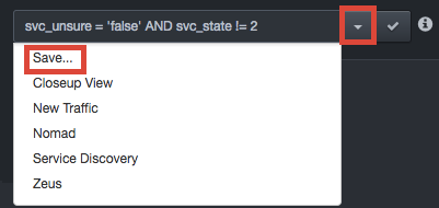
-
At the Save View Filter dialog box, complete the fields:
-
Name = enter a name for this filter. The name should alllow you to identify this filter from any others you saved.
-
Description = enter an optional description for this filter.
-
Filter String = shows the filter. This field allows you to edit the filter. A message appears if your edits result in an invalid filter.
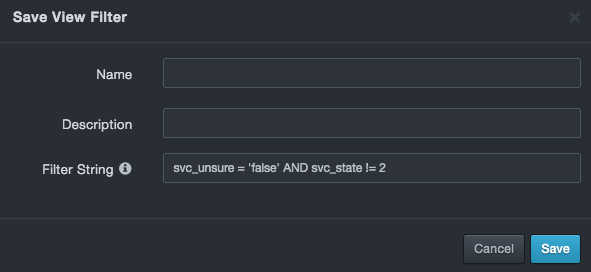
-
-
Click Save. You can now recall the filter using the Settings > View Filters option.
To clear a filter and redisplay all records, delete the criteria in
the filter field, and then click the icon.
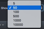
Showing Records
Some pages that show records provide a Show drop-down list at the right side of the page.
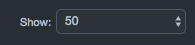
This drop-down list allows you to select the maximum number of records displayed in the table at one time.
Searching Records
Some pages that show records provide a search field at the right side of the page. This field allows you to filter records according to the search criteria entered in this field.
To search records
-
In the Search field, enter your search criteria. When you finish, press Enter. Only records that match your criteria are displayed.
-
To clear the search and redisplay all records, remove the criteria from the Search field and press Enter.
Sorting Records
When the workspace contains a table of records, click a column header to sort the values in that column in ascending (A-Z, 0-9) or descending (Z-A, 9-0) order. The columns can be sorted independently. This means you can sort one column in ascending order and two in descending order, two columns in ascending order and one in descending order, or any other combination. You can also sort multiple columns by holding down the Shift key and clicking multiple columns. An arrow to the right of the column header shows the sorting order:
-
An up arrow indicates ascending sort order. For example:
-
A down arrow indicates descending sort order. For example:
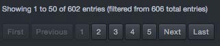
Navigating to Pages within the Workspace
There may be times when the workspace contains a table of records that spans more than one page. In these cases, the total number of entries appears above the table, along with icons you can click to go to the first, previous, next, or last page or a specific page.
Freezing Your View
Pages that provide updated information in the workspace have a Freeze button at the top- right side of the page that allows you to stop the on-screen information from updating automatically.

When you click Freeze, updates to the screen stop and the button toggles to Frozen.

Clicking Frozen resumes updating information to the screen and toggles the button to Freeze.
Refreshing Your View
Some pages provide a Refresh button at the top-right side of the page. Click this button to update the information shown in the workspace. In the Visibility > Services > Service Discovery page, for example, you can click this button to show new database services.

Using the Gear Icon
The right side of most pages contains a gear icon:

Clicking this icon allows you to perform activities specific to the context you are in. The sections below describe the activities you can perform for various contexts.
Configuring Columns
If the page has a table displayed in the workspace, you can configure the table to show or hide columns to view only the information that interests you. You can also arrange the columns in the order you desire.
To configure columns
-
Click the
icon, and then select
Configure columns. A Configure Columns dialog box similar to the
following appears, with two lists:-
All columns shows all the columns you can select.
-
Selected columns shows the columns selected for use.
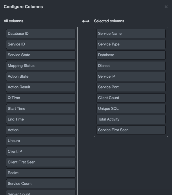
-
-
In the All columns list, select a column you want to appear in the table, and then drag it to the Selected columns list. Repeat this step for each additional column you want shown in the table. If you decide not to use a column, drag it from the All columns list to the Selected columns list.
-
To sort the columns according to the order you want them to appear in the table, click a column in the Selected columns list.
Then drag it up or down in the list:-
Dragging a column up moves it to the left side of the table.
-
Dragging a column down moves it to the right side of the table.
-
-
Click Save.
Saving and Listing Views
If you display certain views frequently, you can save them using the Save view as option. Saved views can be displayed using the Settings > Saved Views option.
To save a view
-
Click the
icon, and then select Save
view as. A Save View dialog box similar to the following appears.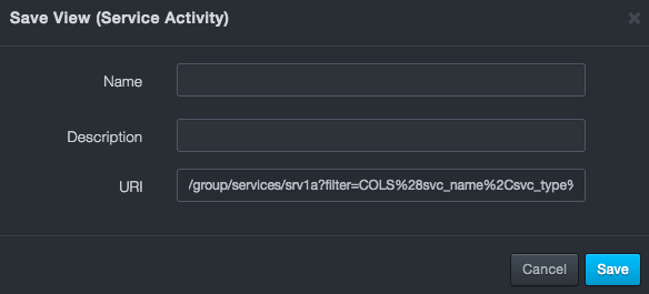
-
Complete the fields (see the table below).
-
Click Save.
Fields in the Save View Dialog Box
| Field | Description |
|---|---|
| Name | Enter a name for this view. The name should allow you to differentiate this view from others you might have saved. |
| Description | Enter a description for this view. |
| URI | Read-only field that shows the URL the view will generate based on the currently set options. |
After you save a view, you can list it for viewing.
To list a view
-
Click the
icon, and then click List
views. -
When a List Views dialog box similar to the following appears, click the
 icon on the far right for the view you
want to see.
icon on the far right for the view you
want to see.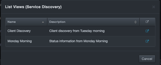
Downloading Tables as CSV Files
Some tables can be exported as comma-separated-value (CSV) files. Exporting a table in CSV format allows you to work with the data using applications that accept CSV files, such as Microsoft Excel.
To download a table as a CSV file
Click the icon, and then click Download as CSV.
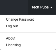
Profile Menu
| This profile menu is the rightmost menu in the web management interface. The name of the menu acquires the name of the logged in user. This section describes the options in the profile menu. |
Changing the Password
Path: profile menu > Change Password
For security, change the default admin password the first time you log in to the web management interface. Thereafter, you can change the password as necessary.
To change a password
-
At the top-right side of the page, click the profile menu, and then select Change Password.
The Change password dialog box appears.
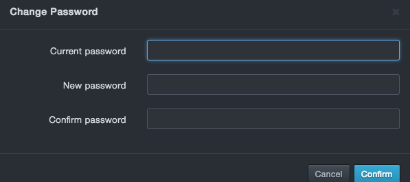
-
In the Current Password field, enter your current log in password. For security, each typed character is masked with a dot (•).
-
In the New Password field, enter your new case-sensitive password. Then retype the same password in the Confirm Password field. For security, each typed character is masked with a dot (•).
-
Click Confirm.
Logging Out
Path: profile menu > Logout
When you finish with your session, click Logout on the profile menu to end your session, log out, and display the log in page.
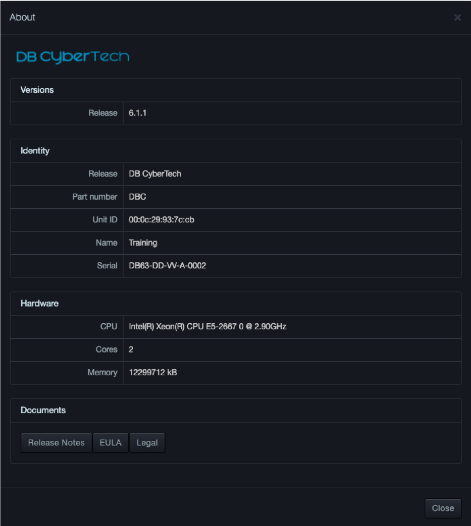
Displaying Version Information
Path: profile menu > About
Clicking About on the profile menu displays a page showing the version number, identity, and hardware information for your system. Buttons below the Documents section allow you to read the latest release notes, end user license agreement (EULA), and legal notices for installed licensed and open-source packages.
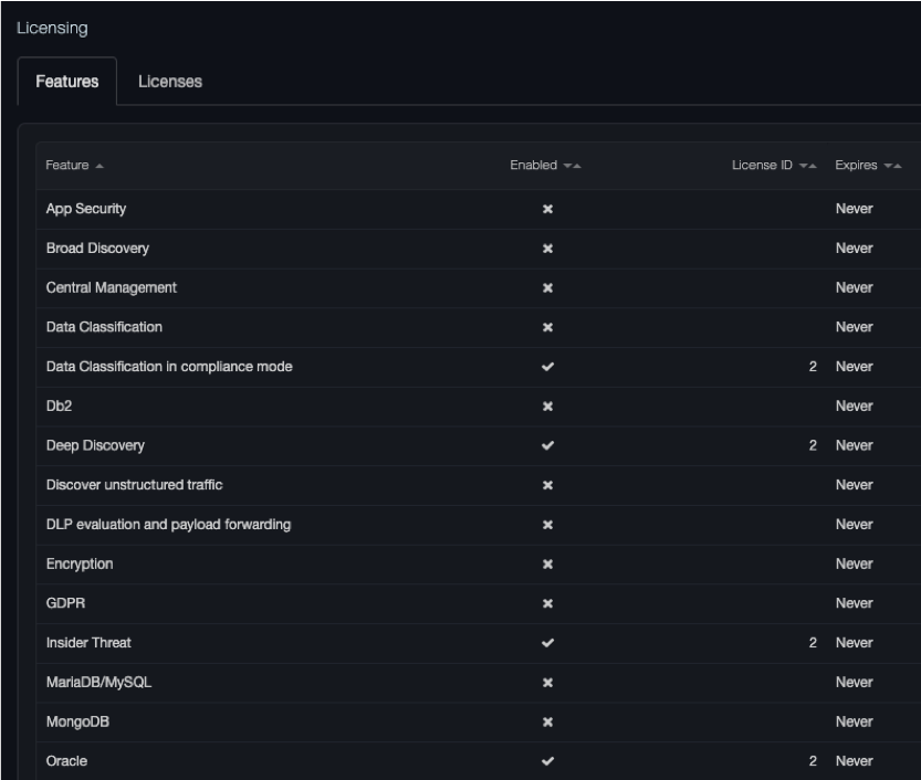
Managing Licenses
Path: profile menu > Licensing
Clicking Licensing on the profile menu displays the Licensing page. This page contains two tabs:
-
Features is a read-only tab that shows the licensed features installed on the platform, their license ID, and the date and time when they expire.

-
The Licenses tab allows you to add licenses.
Adding Licenses
The following procedure describes how to install licenses.
| | Note: All licenses are provided by DB CyberTech. To obtain a new license or obtain details about existing licenses, contact DB CyberTech Technical Support. |
-
At the top-right side of the page, click the profile menu, and then click Licensing.
-
When the Licensing page appears, click the Licenses tab.
-
At the top-left side of the tab, click Add.
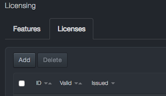
-
In the Add License dialog box, paste the new license you are adding and click Save.
-
The new license appears and the system will request approval to restart
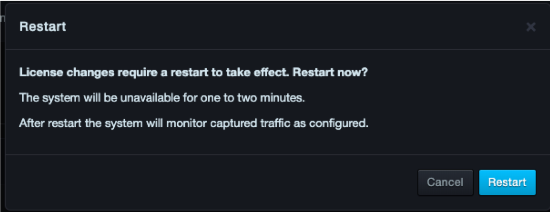
The system alert icon informs you about the number of days when a license is approaching expiration and when it has expired:
-
Starting at 120 days the blue system alert indicator shows the number of days remaining.
-
Starting at 60 days, the orange system alert indicator shows the number of days remaining.
-
Starting at 30 days, the red system alert indicator shows the number of days remaining.
-
Deleting Licenses
If you no longer need a license, you can delete it.
| | Note: A precautionary message does not appear when you delete a license. Therefore, be sure you do not need a license before you delete it. |
To delete a license
-
At the top-right side of the page, click the profile menu, and then click Licensing.
-
When the Licensing page appears, click the Licenses tab.
-
At the right side of the tab, check each license you want to delete.
-
At the top-left side of the tab, click Delete.
-
The system informs you that the license has been removed. The effects of removing a license are applied when you log out of the web management interface, and then log back in.
Settings Menu
| This section describes the options in the Settings menu. |
Configuring Initial Settings
Path: Settings > Initial Configuration
Settings > Initial Configuration provides the following submenus in the left pane:
-
Network — configures the platform IP address.
-
Time — configures the platform system clock.
-
Capture Sources — configures the platform capture port settings.
-
Authentication — configures native and LDAP settings.
-
Security — configures port and certificate settings.
-
CMS – configure options for connecting to a CMS.
Network
Path: Settings > Initial Configuration > Network
The Network page allows you to configure the platform to use a fixed (static) IP address or a dynamically assigned IP address from a Dynamic Host Configuration Protocol (DHCP) server.
Using a Static IP Address
To have the platform use a static IP address
-
Click Settings > Initial Configuration.
-
In the left pane, click Network. The Network page appears.
-
For Type, click Static. The following fields appear.
-
Complete the fields.
-
Click Commit.
Static IP Address Fields in the Network Page
| Field | Description | Default |
|---|---|---|
| Unit Name | Name that will appear at the top of the user interface | See the GUI |
| IP Address | Static IP address you want to assign to the system | See the GUI |
| Subnet Mask | Subnet mask you want to assign to the system | 255.255.255.0 |
| Default Gateway | Default gateway for reaching beyond the local network | See the GUI |
| Enable DNS | Enables or disables the device’s Domain Name System (DNS) capabilities | Disabled |
| Primary DNS | If your configuration uses DNS to resolve IP addresses (for example, the IP address for the NTP server used with the system), enter the primary DNS server setting. | 8.8.8.8 |
| Secondary DNS | Enter the IP address for the secondary DNS server. If the primary DNS server does not answer a request, the system sends the request to the secondary DNS server. | — |
Using a DHCP-Assigned IP Address
To configure the platform to receive an IP address from a DHCP server
-
Click Settings > Initial Configuration.
-
In the left pane, click Network. The Network Page appears.
-
For Type, click DHCP. The following field appears.
-
In the Unit Name field, enter the name that will appear at the top of the user interface.
-
Click Commit.
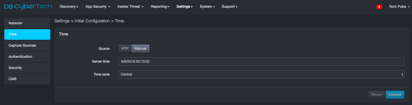
Time
Path: Settings > Initial Configuration > Time
Using the Time page, you can configure the platform to synchronize its system clock with a Network Time Protocol (NTP) server or set the system time manually.
Configuring the System to Use an NTP Server
To configure the platform to use an NTP server
-
Click Settings > Initial Configuration.
-
In the left pane, click Time. The Time page appears.
-
Next to Source, click NTP. The following fields appear.
-
Complete the fields.
-
Click Commit.
NTP Fields in the Time Page
| Field | Description | Default |
|---|---|---|
| NTP server | Enter the IP address of the NTP server. | 0.0.0.0 |
| Status | Read-only field that shows “Contacted” when the platform connects with the NTP server whose IP address is specified in the “NTP Server” field. | — |
| Time zone | Select the time zone where the platform is located. | Central |
Configuring Time Manually
To configure system time manually
-
Click Settings > Initial Configuration.
-
In the left pane, click Time. The Time page appears.
-
Next to Source, click Manual. The following fields appear.
-
Complete the fields.
-
Click Commit.
Manual Time Fields in the Time Page
| Field | Description | Default |
|---|---|---|
| Server Time | Enter the date and time to be used by the platform in a 24 hour clock format | See GUI |
| Time Zone | Select the time zone where the system is located | Central |
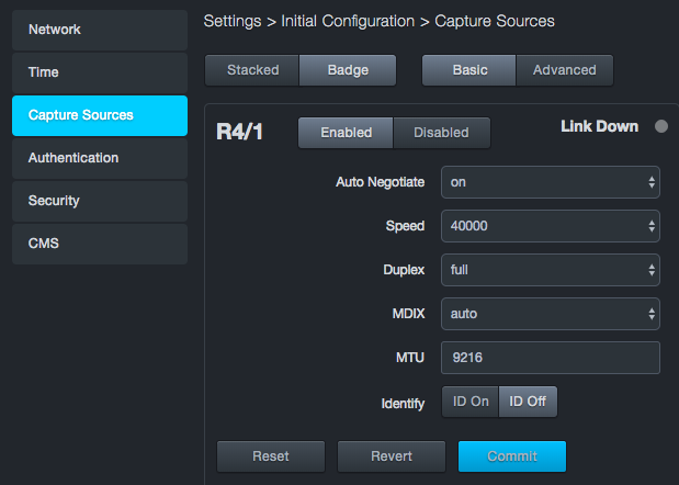
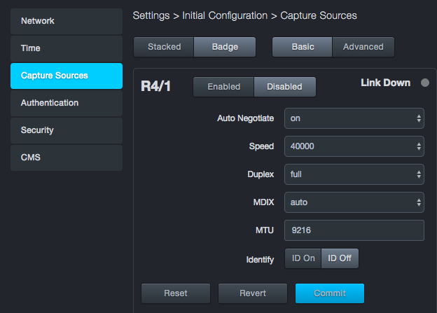
Capture Sources
Path: Settings > Initial Configuration > Capture Sources
The Capture Sources page shows the current status of all capture ports identified by the software. Each port appears as a sub-page in the Capture Sources page. You can arrange the sections to appear in a stacked or badge layout using the Stacked and Badge buttons at the top-left side of the Capture Sources page. The top of the page also has Basic and Advanced buttons you can click to view and set the basic and advanced settings for each capture port.
At the top-left side of each section are Enabled and Disabled buttons for enabling or disabling the respective port. The top-right of each section has a Link Down indicator that lights if the link goes down. If you suffer from a link-down condition, contact DB CyberTech Technical Support.
The bottom-left side of each section has buttons to perform a factory reset of the port, revert to the port settings to their original state before you changed settings, and commit changes you make to the port configuration.
|  | Warning: If you perform a factory reset, all user and configuration data is deleted, and the admin IP address reverts to the one on the DB-6300 serial number sticker. |
Selecting a Layout
The capture port information can be presented in a badge or stacked layout. Use the Stacked and Badge buttons at the top of the Capture Sources page to toggle between the two layouts.
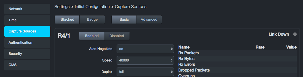
Badge layout places the ports on the top row and the basic or advanced settings on the next row. Badge is the default layout.
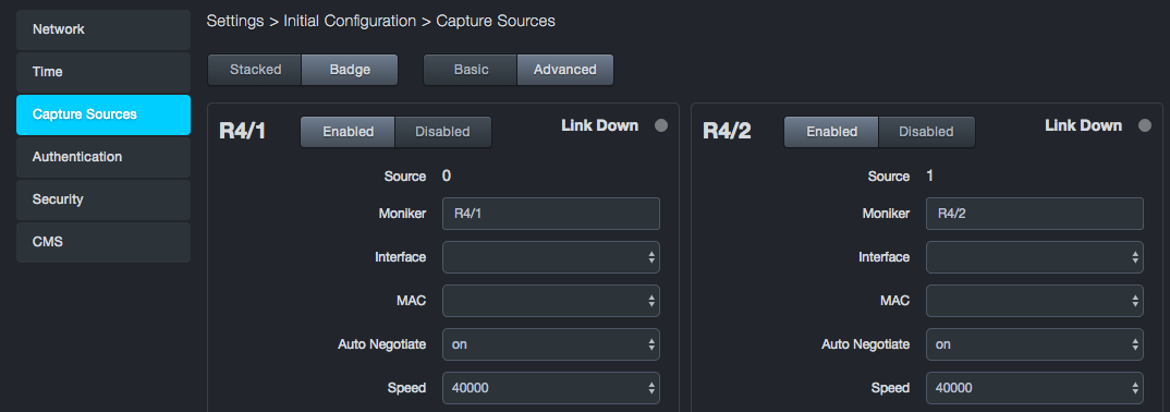
Stacked layout stacks capture ports 1 and 2 over ports 3 and 4 at the left side of the page. Basic or advanced settings appear at the far right.
Enabling or Disabling Capture Ports
You can enable or disable the four capture ports independently.
To disable a capture port
-
Click Settings > Initial Configuration.
-
In the left pane, click Capture Sources. The Capture Sources page appears.
-
At the top of the appropriate section, click the Disabled button for the port.
-
At the bottom of the section, click Commit.
To enable a capture port
-
Click Settings > Initial Configuration.
-
In the left pane, click Capture Sources. The Capture Sources page appears.
-
At the top of the appropriate section, click the Enabled button for the port you want to enable.
-
At the bottom of the section, click Commit.
Configuring Basic and Advanced Settings
Each capture port has a set of basic settings and advanced settings that you can configure. Use the Basic and Advanced buttons at the top of the Capture Sources page to display the basic or advanced settings for all four ports.
The tables below descibe the basic settings and advanced settings. Some settings are user-configurable, while others are read-only values. If you change a port’s configuration settings, click Commit at the bottom-left of the section to apply the changes.
Basic Capture Port Settings
| Field |
|---|
| The following settings are user-configurable |
| Auto Negotiate |
| Speed |
| Duplex |
| MDIX |
| MTU |
| Identity |
| The following read-only fields appear to the right of (stacked view) or below (badge view) the user-configurable settings |
| Rx Packets |
| RxBytes |
| Rx Errors |
| Dropped Packets |
| Overruns |
| Frame Errors |
| Current Speed |
| Duplex Mode |
| Auto Negotiate Mode |
| MDIX State |
| Media |
Advanced Capture Port Settings
| Field |
|---|
| The following settings are user-configurable |
| Source |
| Moniker |
| Interface |
| MAC |
| No Phy |
| GRO |
| LRO |
| Snap Length |
| Version |
| Block MBytes |
| Block Count |
| Block Timeout |
| Identify |
Authentication
Path: Settings > Initial Configuration > Authentication
The Authentication page allows you to configure native and LDAP-based authentication settings.
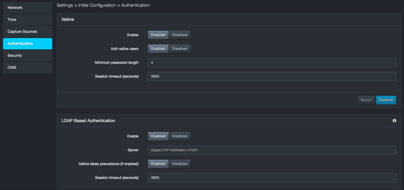
Configuring Native Authentication
To configure native authentication
-
Click Settings > Initial Configuration.
-
In the left pane, click Authentication. The Authentication page appears.
-
Complete the fields in the Native section of the Authentication page.
 4. Click Commit in the Native section
of the page.
4. Click Commit in the Native section
of the page.
Native Fields in the Authentication Page
| Field | Description | Default |
|---|---|---|
| Enable | Enables or disables native user authentication | Enabled |
| Add native users | Enables or disables creation of native users. | Enabled |
| Minimum password length | Minimum number of characters required for a valid password. | 4 |
| Session timeout (seconds) | Number of seconds that must elapse before the platform logs out the user automatically. | 3600 |
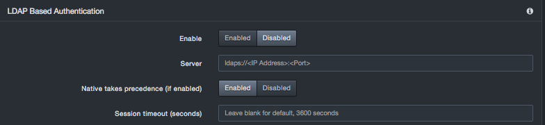
Configuring LDAP Authentication
You can configure the platform to use a LDAP directory for user and role configuration. The system provides a built-in LDAP directory connector for Microsoft Active Directory. The system constructs a Distinguished name (DN) based on the configuration entered by the admin and the username entered by the user. It uses this DN to try and bind to the LDAP directory for authorization. If the bind is successful, that user’s object will be searched for attributes, such as display name and users groups. Groups returned for that user are then checked against the authorized group list to determine user roles.
The authorized group list is given to the system during the LDAP configuration procedure.
-
If a user is not in any authorized groups, the user will not be able to log in to the system.
-
If the user is in an authorized group, the user will be assigned privileges consistent with the role to which the user is mapped.
LDAP Directory Configuration
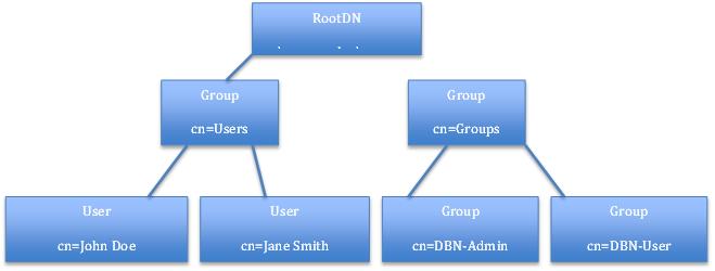
User objects typically are found under a group called Users. The Users group is under the rootDN in the LDAP directory.
Example DN: The unit construct to bind and search for user information would be cn=John Doe,cn=Users,dc=example, dc=com where:
-
John Doe is the username entered at log in, and
-
dc=example,dc=com is the rootDN of the LDAP Directory that is configured at setup.
The following figure shows an example of the supported structure.
The platform reads only information from the LDAP directory, so all changes about user information and the groups users must be made on the LDAP directory server.
User Object
The user object on the LDAP server is expected to have the following attributes for successful authorization and authentication:
-
dn = distinguished name by which the system can search in the format described above.
-
memberOf = groups to which the user belongs. This field is used to determine user roles on the system.
The following is an example of user information returned from LDAP directory server for a user.
# John Doe, Users, example.com
dn: CN=John Doe,CN=Users,DC=example,DC=com
cn: John Doe
displayName: John Doe
memberOf: CN=DBN-Admin,CN=Builtin,DC=example,DC=com
LDAP Authentication Options
To configure LDAP authentication
-
Click Settings > Initial Configuration.
-
In the left pane, click Authentication. The Authentication page appears.
-
Complete the fields in the LDAP Based Authentication section of the Authentication page.
-
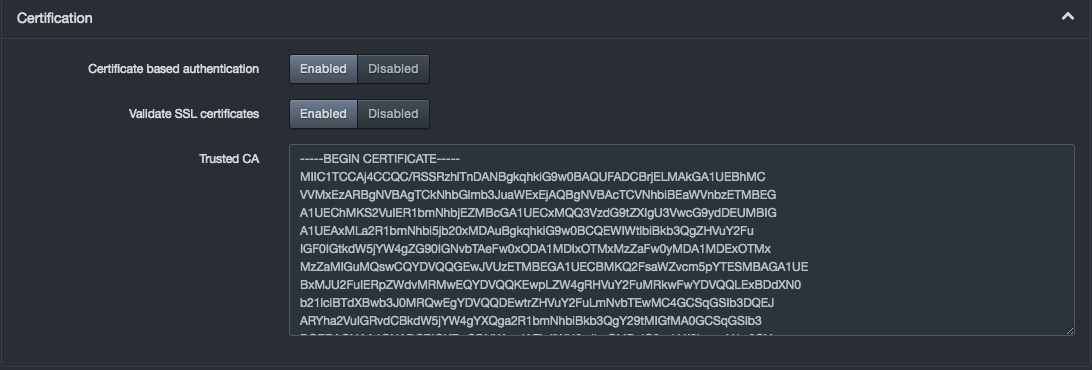
To use certificates, click Certification and complete the settings.
-
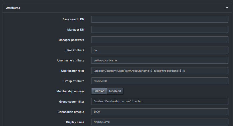
To use attributes, click Attributes and complete the settings.
-
To map roles to groups, click Role to Group Mapping and complete the settings.
-
Click Commit in the LDAP section of the page.
LDAP Based Authentication Fields in the Authentication Page
| Field | Description | Default |
|---|---|---|
| Enable | Enable or disables LDAP | Disabled |
| Server | Hostname or IP address of LDAP directory server, entered as a complete URI. | - |
| Native takes precedence (if enabled) | Indicates whether LDAP or Local auth is queried first when a user logged in | Enabled |
| Session timeout (seconds) | Number of seconds that must elapse before the platform logs the user out automatically | 3600 |
Certification Settings
| Field | Description | Default |
|---|---|---|
| Certificate based authentication | Enables or disables certificate-based authentication | Enabled |
| Valid SSL certificates | Enables or disables the use of SSL certificates. | Enabled |
| Trusted CA | Paste the certified key from the certificate authority. | |
Attributes Settings
| Field | Description | Default |
|---|---|---|
| Base Search DN | Base directory to start searching for users and groups. If the directory is blank, the system will try auto-populating the directory. | |
| Manager DN | Fully distinguished name of an authorized LDAP user to query the LDAP server. | |
| Manager password | Manager DN's LDAP password. | |
| User attribute | Attribute used to find users. | cn |
| User name attribute | Attribute field to use on the user object. | |
| User search filter | Filter to use when searching user objects. | |
| Group attribute | Attribute used to find group membership on a user object or to query LDAP server. | |
| Membership on user | Accept the default setting of Enabled if a user's groups are returned with the user object. Change this setting to Disabled to use the Group search filter option. | Enabled |
| Group search filter | Filter to use when searching group objects. This setting applies only if the Membership on user option is disabled. | |
| Connection timeout | Number of milliseconds before timing out an attempted connection to the LDAP server. | 6000 |
| Display name | Attribute on the user object that contains the display name of the user. | |
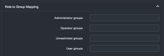
Role to Group Mapping Settings
| Field | Description | Default |
|---|---|---|
| Administrator groups | List of comma-separated administrator groups on the LDAP server whose users will be given administrator privileges on the system. | |
| Operator groups | List of comma-separated operator groups on the LDAP server whose users will be given operator privileges on the system. | |
| Unrestricted groups | List of comma-separated unrestricted groups on the LDAP server whose users will be given unrestricted privileges on the system. | |
| User groups | List of comma-separated user groups on the LDAP server whose users will be given user privileges on the system. | |
Security
Path: Settings > Initial Configuration > Security
The Security page allows you to use a certified key pair and SSL settings to force the platform to use SSL. You can also enable or disable certain user-interface ports on the platform, enable or disable strict transport security HTTP header settings, enable or disable global redaction settings, and force two-factor authentication for the shell password.
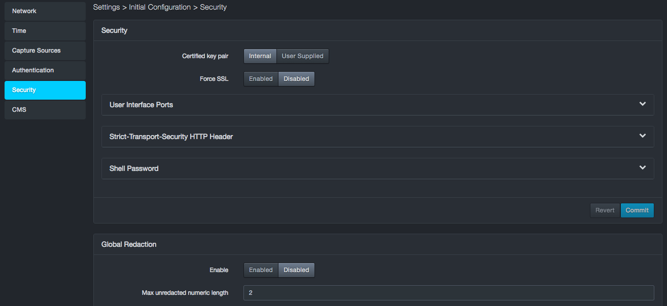
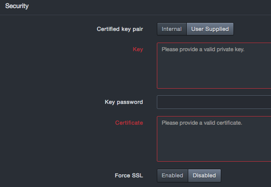
Configuring Security Settings
The Security panel allows you to configure settings for certified key pair and SSL.
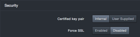
Security Settings
| Field | Description | Default |
|---|---|---|
| Certified Key Pair | Allows you to use a key pair generated by the platform or your own key pair. If you select User Supplied, complete the following fields
|
Internal |
| Force SSL | Enables or disables an SSL connection. | Enabled |
Enabling or Disabling User Interface Ports
To safeguard the platform module, you should install it on a protected internal network. Although the platform is configured to have only the necessary user interface ports available, you must make sure that attacks cannot reach it from outside the firewall.
Open ports allow:
-
Access to the platform user interface
-
Secure remote connections to the platform
-
Certain features to access the local or Internet resources they need to function correctly
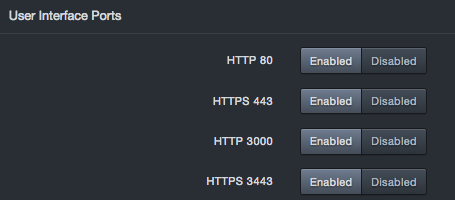
By default, all user interface ports on the platform are enabled. There might be times when you want to disable some of these ports. Expanding the User Interface Ports section on the security page provides settings you can use to enable (open) or close (disable) the following ports on the DB-6300 user interface:
-
HTTP port 80
-
HTTPS 443
-
HTTP port 3000
-
HTTPS port 3443
You cannot disable all four user interface ports.
To access this feature, expand the User Interface Ports panel on the Security page. At least one port must be open. If you change these settings, click Confirm.
Configuring Strict Transport Security HTTP Header Settings
The platform supports an HTTP strict transport security response header security feature that allows the appliance to tell browsers that they should communicate with the appliance using HTTPS instead of HTTP. This feature allows the platform to inform the browser that it should never communicate with the appliance using HTTP and should automatically convert all attempts to access the appliance using HTTP to HTTPS requests instead.
To access this feature, expand the Strict-Transport-Security HTTP Header panel on the Security page. If you change these settings, click Confirm.
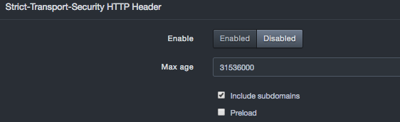
Strict Transport Security HTTP Header Settings
| Field | Description | Default |
|---|---|---|
| Enable | Enables or disables the strict transport security HTTP header feature.
|
Disabled |
| Max age | Time, in seconds, that the browser should remember the platform is only to be accessed using HTTPS. | 31536000 (1 year) |
| Include subdomains | Determines whether this setting applies to all subdomains.
|
Checked |
| Preload | Determines whether the platform domains are added to Chrome's HTTP Strict Transport Security (HSTS) preload list. This is a list of sites that are hardcoded into Chrome as being HTTPS only.
|
Unchecked |
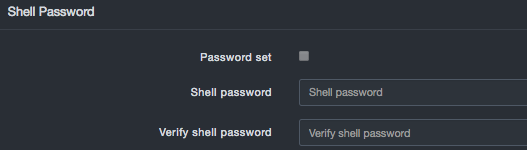
Shell Password
The Shell Password panel allows you to set or change the shell password.
The shell password that you specify here can be combined with a factory-generated key known only to DB CyberTech to generate a “final” password that DB CyberTech Technical Support personnel can use to conduct a shared screen session with the customer.
Shell Password Settings
| Field | Description | Default |
|---|---|---|
| Password set | Allows you to specify whether you are setting the shell password.
|
Unchecked |
| Shell password | Case-sensitive shell password known only to the customer. For security, each typed character is masked with a dot (•). | |
| Verify shell password | Same case-sensitive shell password entered in the “Shell password” field. For security, each typed character is masked with a dot (•). | |
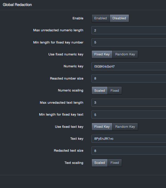
Global Redaction
The Global Redaction panel allows you to place all newly discovered databases into redaction based on the settings configured in this panel. By default, this feature is disabled. If you enable and configure this feature, and then click Commit, a warning message tells you that you must clear all user data before the settings can go into effect.
Enabling global redaction affects newly discovered databases only. Existing databases will not be redacted. If a database was already configured for redaction, those settings are not affected. If a database is subsequently configured, the individual setting for that database will override the global setting. For example, if global redaction is enabled and an individual database is configured with redaction off, the database will not be redacted. Disabling global redaction turns it off only for databases that were not previously configured on the database setting screen.
Global Redaction Settings
| Field | Description | Default |
|---|---|---|
| Enable | Enables or disables the global redaction feature.
|
Disabled |
| Max unredacted numeric length | Numeric fields with less than or equal to this number of digits will be left unredacted | 2 |
| Min length for fixed key number | Minimum number of digits present to allow use of a fixed key. Numbers shorter than this but greater than the unredacted max length are hashed with a random key per statement. The same number hashed thus will differ between statements but will be the same within a single statement. | 5 |
| Use fixed numeric key | Allows you to select a fixed key or random key.
|
Fixed Key |
| Numeric key | If “Use fixed numeric key” is set to “Fixed key,” enter the key you wish to use. | See the GUI |
| Redacted number size | Numeric fields will be no longer than this size, they be shorter if Numeric Scaling is enable. | 8 |
| Numeric scaling | Allows you to select a scaled or fixed scaling.
|
Scaled |
| Max unredacted text length | Character fields with less than or equal to this number of digits will be left unredacted | 3 |
| Min length for fixed key text | Minimum characters present in a string to allow use of the fixed text key. Strings shorter than this but greater than the unredacted max length are hashed with a random key. The same string hashed thus will differ between statements but will be the same within a single statement. | 5 |
| Use fixed text key | Allows you to select a fixed key or random key. Fixed key = key assigned by the user. If you select this setting, complete the “Text key” field. Random key = A key generated by the system |
Fixed Key |
| Text key | If “Use fixed text key” is set to “Fixed key,” enter the key you want to use. | See the GUI |
| Redacted text size | Text fields will be no longer than this size. They may be shorter if text scaling is enabled | 8 |
| Text scaling | Allows you to select scaled or fixed text scaling.
|
Scaled |
CMS
Path: Settings > Initial Configuration > CMS
The CMS panel allows you to set configurations on the system to connect to a DB CyberTech CMS server. For more information on the CMS, see the CMS user's guide.
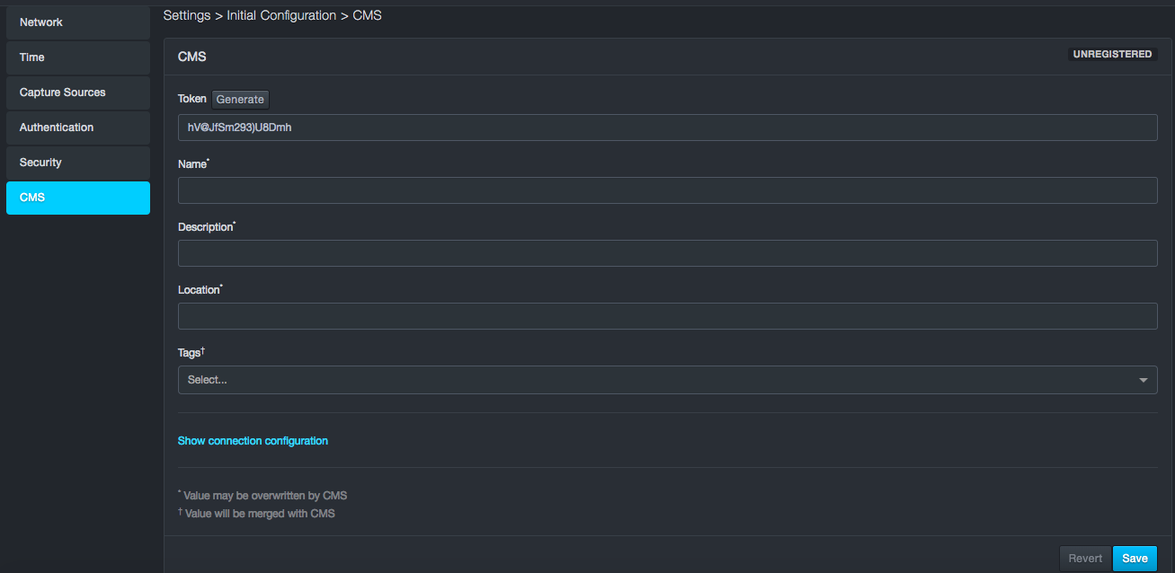
CMS Configurations
| Field | Description |
|---|---|
| Registered/Unregistered | Shows the current status of connection to the CMS system |
| Token/Generate | Token to establish secure connection with the unit |
| Name | Name of the unit for display in the CMS |
| Description | Description of the unit for display in the CMS |
| Location | Location of the unit for display in the CMS |
| Tags | Options assigned to the unit by the CMS |
| Connection configuration | IP address, Port, Protocol – TCP or UDP |
Managing Users, Roles, and API Keys
Path: Settings > User Management
Settings > User Management provides the following submenus in the left pane:
-
Users — creates, edits, and deletes system users.
-
Roles — creates, edits, and deletes user roles.
-
API Keys — creates, imports, edits, and deletes API keys.
Managing Users
Path: Settings > User Management > Users
The platform comes with one predefined account called admin, which has Administrator privileges. Using the Users page, you can add users. After a user is added, you can edit or delete the user.
Creating New Users
To create a new user
-
Click Settings > User Management. The Users page appears.
-
At the top-left side of the page, click New User. The New User dialog box appears.
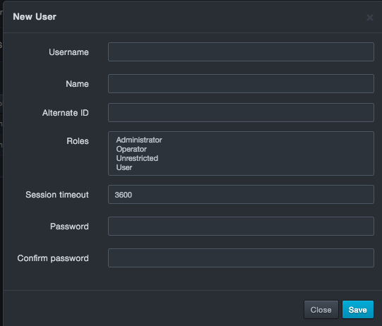
-
Complete the fields.
-
Click Save. The user is added to the Users page.
Fields in the New/Edit User Dialog Box
| Field | Description | Default |
|---|---|---|
| Username | New User dialog box: enter the name used to log in to the system. Edit User dialog box: read-only field that shows the name used to log in to the system. |
— |
| Name | Name of the new user. Duplicate last names are not allowed. | — |
| Alternate ID | If logging in using a certificate (such as the certificate on a CAC card), enter the certificate number. | — |
| Roles | Roles this user will have within the system. Choices are:
|
|
| Session timeout | Number of seconds that must elapse before the platform logs out the user automatically. | 3600 |
| Password | Case-sensitive password this user uses to log in to the web management interface. For security, each typed character is masked with a dot (•). | — |
| Confirm password | Same case-sensitive password entered in the “Password” field. For security, each typed character is masked with a dot (•). | — |
Editing Users
There might be times when you need to edit a user. For example, you might want to change the user’s password.
To edit a user
-
Click Settings > User Management. The Users page appears.
-
On the right side of the page, click the
 icon for the user you want to edit.
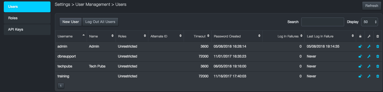
-
An Edit User dialog box similar to the following appears.
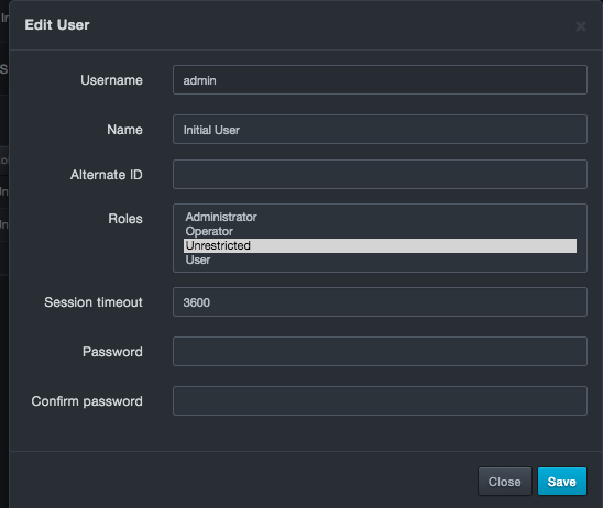
-
Complete the fields you wish to edit.
-
Click Save.
Deleting Users
There might be times when you no longer need a user. In these cases, you can delete the user from the system.
To delete a user
-
Click Settings > User Management. The Users page appears.
-
On the right side of the page, next to the
icon, click the  icon for the user you want
to delete. A message asks whether you are sure you want to delete
the user.
icon for the user you want
to delete. A message asks whether you are sure you want to delete
the user. -
Click Delete to delete the user (or click Cancel to retain the user).
Logging Out Individual Users
Each user on the Users page has a lock icon. You can use this icon to deny users login privileges without having to delete the user.
-
To lock out a user, click the lock icon so it appears like this:

-
To unlock a user, click the lock icon so it appears like this:

Logging Out All Users
The Users page has a Log Out All Users button that allows you to log out every user that is currently logged in to the system. When you click this button, a message asks you to confirm your selection. Click Log Out All Users to continue or click Cancel to cancel the operation.
Managing Roles
The platform comes with a user role management system that defines what a specific user can and cannot do within the web management interface. This is done in a 2-layer fashion. The first layer consists of a number of specific permissions that equates to tasks on the DBN-3600. These permissions are grouped into roles that can be assigned to users. Knowing these user roles and permissions helps to enable following principle of least privilege.
You manage roles using the Settings > User Management > Role page. Understanding these user roles and permissions is essential to keeping your environment safe as the number of users grows.
Out of the box, the platform supports the following roles:
-
Administrator
-
Operator
-
Unrestricted
-
User
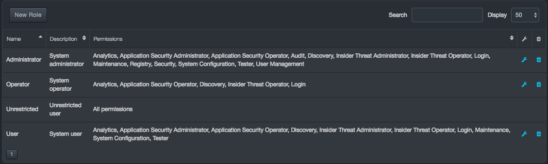
You can accept these roles as they are or change them to suit your requirements. The tables below describe the permissions associated with these roles and matches the bulleted items in the “Permissions Assigned to This Role” column with their capabilities.
Matching Roles and Permissions
| Role | Permissions Assigned to This Role | |
|---|---|---|
| Administrator |
|
|
| Operator |
|
|
| Unrestricted | All permissions | |
| User |
|
|
The initial admin user is assigned the Unrestricted role. This role cannot be edited or deleted through the web management interface. However, it can be modified using the command-line interface. To avoid situations where the platform becomes “stuck” with no ability to recover, the Unrestricted role cannot be deleted using the web management interface. The initial admin user can be assigned to a different role, effectively disassociating that user from the Unrestricted role allowing it to continue to exist if needed but not be actively assigned. Should the need arise and you’re confident in your role mappings, the Unrestricted role can be deleted using the command-line interface (CLI).
To display the Settings > User Management > Role page
-
Log in to the web interface.
-
On the Settings menu, click User Management.
-
In the left pane, click Roles. A Roles page similar to the following appears. The first time this page appears, the predefined roles of Administrator, Operator, Unrestricted, and User appear. The Permissions column shows the permissions that correspond to each role in the Name column, and the Description column describes the roles.
Fields at the top-right of the page allow you to search roles in the page and select the maximum number of roles you want displayed (default is 50 roles).
Creating New Roles
You can add new roles to the predefined roles that come with the system.
To create a new role
-
Click Settings > User Management. The Users page appears.
-
In the left pane, click Roles. The Roles page appears.
-
At the top-left side of the Roles page, click New Role. The New Role dialog box appears.
-
Complete the fields in the dialog box.
-
Click Save. The profile appears on the Roles page.
Fields in the New/Edit Role Dialog Box
| Field | Description |
|---|---|
| Name | Enter a unique name for this role that has not been assigned to any other role. The name should allow you to differentiate this role from others you might have saved. |
| Description | Enter a description for this role. |
| Permissions | Select all the permissions you want to assign to this role. Use the Shift+click and Ctrl+click keyboard shortcuts to select multiple permissions. For a list of the capabilities that correspond to these permissions. |
Permission Descriptions
| This Permission… | Allows Users to… |
|---|---|
| Analytics |
|
| Application Security Administrator |
|
| Application Security Operator | View SQL events, learned SQL statements, and SQL blacklists. |
| Audit | Export and delete the audit log. |
| Visibility |
|
| Insider Threat Administrator | Configure insider threat policy rules. |
| Insider Threat Operator |
|
| Login | Configure user log in and password settings. |
| Maintenance |
|
| Registry | Read from and write to the registry. |
| Security |
|
| Support |
|
| System Configuration |
|
| Tester | Enable diagnostic and support functions. |
| User Management |
|
Editing Roles
After you create roles, you can edit them if necessary. Except for Unrestricted, you can also edit the predefined roles.
To edit a role
-
Click Settings > User Management. The Users page appears.
-
In the left pane, click Roles. The Roles page appears.
-
On the right side of the Roles page, click the
icon for the role you want to edit. An
Edit Role dialog box similar to the following appears.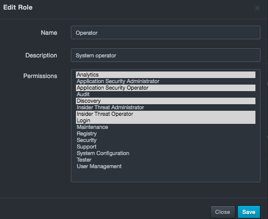
-
Complete the fields in the dialog box.
-
Click Save. The profile appears in the Roles page, with the revised permissions shown in the Permissions column.
Deleting Roles
There might be times when you no longer need a role. In these cases, you can delete the role from the system.
To delete a role
-
Click Settings > User Management. The Users page appears.
-
In the left pane, click Roles. The Roles page appears.
-
At the top-right side of the Roles page, click the
icon for the role you want to delete. A
message asks whether you are sure you want to delete the role. -
Click Delete to delete the role (or click Cancel to retain it).
Assigning Roles to LDAP Groups
After you create new roles, you can add them to your LDAP configuration by entering the role names in the Role to Group Mapping fields in the Settings > Initial Configuration > Authentication page. For more information about configuring LDAP.
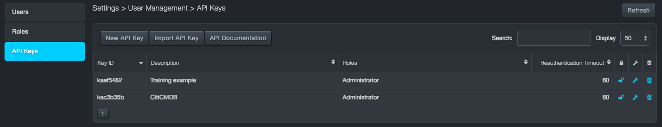
Managing API Keys
Path: Settings > User Management > API Keys
API keys allow you to create scripts that fetch information from the platform. Using the API Keys page, you can add and import API keys. After an API key is added, you can edit or delete the API key.
Creating New API Keys
Path: Settings > User Management > API Keys
To create a new API key
-
Click Settings > User Management. The Users page appears.
-
In the left pane, click API Keys. The API Keys page appears.
-
At the top-right side of the API Keys page, click New API Key. The New API Key dialog box appears.
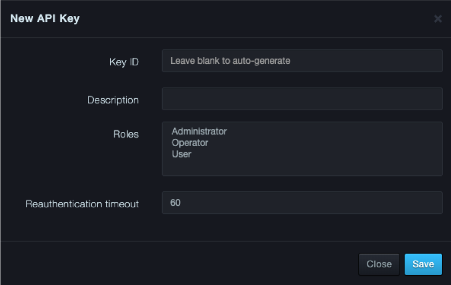
-
Complete the fields.
-
Click Save. A message requests you to copy the information because the password and API key cannot be retrieved at a later time.
-
After recording the information, click Close to close the message box. The API key is added to the API Keys page.
Fields in the New/Edit API Keys Dialog Box
| Field | Description | Default |
|---|---|---|
| Key ID | New API Key dialog box: enter an ID to identify this API key. Edit API Key dialog box: read-only field that shows the ID associated with the API key. |
— |
| Description | Description of the API key. | — |
| Roles | Roles this API will have within the system. Choices are:
|
|
| Reauthentication Timeout | Number of seconds that must elapse before platform forces the user to reauthenticate automatically. | 60 |
Importing New API Keys
To import API keys
-
Click Settings > User Management. The Users page appears.
-
In the left pane, click API Keys. The API Keys page appears.
-
At the top-right side of the API Keys page, click Import API Key. The Import API Key dialog box appears.
-
Complete the fields.
-
Click Save.
Fields in the Import API Keys Dialog Box
| Field | Description | Default |
|---|---|---|
| API Key | Number of the API key you want to import. | — |
| Description | Description of the API key. | — |
| Roles | Role that will be inherited by the imported API. | — |
| Reauthentication Timeout | Number of seconds that must elapse before the platform forces the user to reauthenticate automatically. | 60 |
Editing API Keys
There might be times when you need to edit an API key. For example, you might want to change the API key description or role.
To edit an API key
-
Click Settings > User Management. The Users page appears.
-
In the left pane, click API Keys. The API Keys page appears.
-
On the right side of the API Keys page, click the
 icon for the API key you want to edit. An
Edit API Key dialog box similar to the following appears.
icon for the API key you want to edit. An
Edit API Key dialog box similar to the following appears.
-
Complete the fields.
-
Click Save.
Locking or Unlocking API Keys
Each API key on the API Keys page has a lock icon. You can use this icon to lock or unlock an API key from being authenticated.
-
To lock an API key, click the lock icon so it appears like this:
-
To unlock an API key, click the lock icon so it appears like this:
Deleting API Keys
There might be times when you no longer need an API key. In these cases, you can delete the API key from the system.
To delete an API key
-
Click Settings > User Management. The Users page appears.
-
In the left pane, click API Keys. The API Keys page appears.
-
On the right side of the page, click the
icon for the API key you want to delete. A message asks whether you
are sure you want to delete the API key. -
Click Delete to delete the API key (or click Cancel to retain the API key).
Saved Views
Path: Settings > Saved Views
Using the Saved Views page, you can display the views you saved using the Save view as option located in the gear icon in various pages. You can also edit and delete saved views from the Saved Views page.
Viewing Saved Views
To view a saved view
- Click Settings > Saved Views. The Saved Views page lists the views you have saved.
Displaying Saved Views
To display a saved view
-
Click Settings > Saved Views. The Saved Views page lists the views you have saved.
-
On the right side of the page, click the
 icon that corresponds to the saved view you want to view. The system
displays the saved view.
icon that corresponds to the saved view you want to view. The system
displays the saved view.
Editing Saved Views
There might be times when you want to edit a saved view. For example, you might want to change the name or description of the saved view.
To edit a saved view
-
Click Settings > Saved Views. The Saved Views page lists the views you have saved.
-
On the right side of the page, click the
icon that corresponds to the saved view you want to edit. The Save
View dialog box appears.
-
Change the name and description as desired. You cannot change the URI.
-
Click Save.
Deleting Saved Views
If you no longer need a saved view, you can delete it from the system.
To delete a saved view
-
Click Settings > Saved Views. The Saved Views page lists the views you have saved.
-
On the right side of the page, click the
 icon that corresponds to the saved view you want to delete. A message asks whether you are sure you want to delete the saved view.
 -
Click Delete to delete the saved view (or click Cancel to retain it).
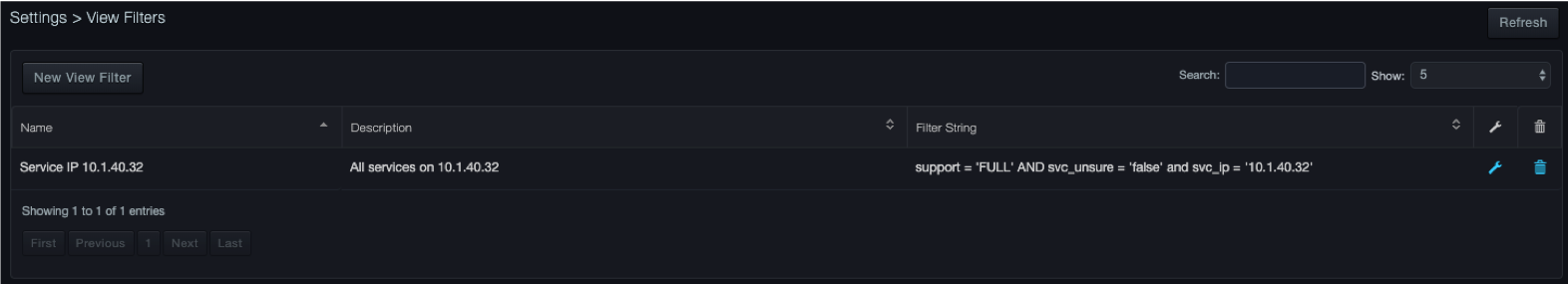
Working with View Filters
Path: Settings > View Filters
Using the View Filters page, you can display the view filters you saved using the Save option selected from the Filter drop-down list:
You can also edit and delete saved view filters from the View Filters page.
Viewing Saved View Filters
To view a saved view filter
-
Click Settings > View Filters. The View Filters page lists the filters you have saved. For example:
Editing Saved View Filters
There might be times when you want to edit a saved view filter. For example, you might want to change the filter name, description, or string.
To edit a saved view filter
-
Click Settings > View Filters. The View Filters page lists the view filters you have saved.
-
On the right side of the page, click the
icon that corresponds to the saved view filter you want to edit. The Save View Filter dialog box appears.
-
Change the name, description, and filter string as desired. An error message appears if the syntax of the edited filter string is not valid.
-
Click Save.
Deleting Saved View Filters
If you no longer need a saved view filter, you can delete it from the system.
To delete a saved view filter
-
Click Settings > View Filters. The Filters page lists the view filters you have saved.
-
On the right side of the page, click the
icon that corresponds to the saved view filter you want to delete. A message asks whether you are sure you want to delete the saved view filter. -
Click Delete to delete the view filter (or click Cancel to retain it).
Configuring Advanced Settings
Path: Settings > Advanced
Settings > Advanced provides the following submenus in the left pane:
-
Capture Filters — configures the platform to monitor or ignore a range of IP addresses within a defined IP realm.
-
Syslog — configures syslog settings.
-
Audit Log — downloads audit log information, turns the audit log on or off, and selects the categories that appear in the audit log.
-
Capture VLAN — defines the realms.
-
CMDB – allows the user to import, configure, and load CMDB data to the platform.
Capture Filters
Path: Settings > Advanced > Capture Filters
The Capture Filters page allows you to configure capture filters. For convenience, you can configure capture filter settings using basic or advanced mode.
-
Basic mode allows you to specify settings using fields in the IP Range dialog box.
-
Advanced mode allows you to build filters using Berkley Packet Filter (BPF) syntax.
|  | Note: Switching from one mode to another discards all settings configured in the mode you are leaving. |
Using Basic Mode to Configure Capture Filters
When you use the basic method to configure capture filters, you specify an IP realm, range of IP addresses, and range of ports in the IP Range dialog box. The system takes the values you specify and converts them to BPF format automatically.
To configure capture filters using basic mode
-
Click Settings > Advanced.
-
In the left pane, click Capture Filters. The Capture Filters page appears
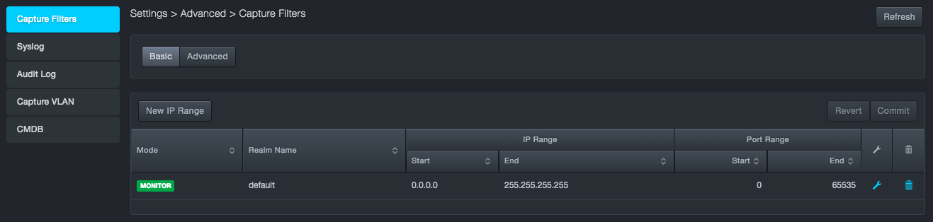
-
At the top-left side of the page, confirm that the Basic button is selected.
-
Below the Basic button, click New IP Range. The IP Range dialog box appears.
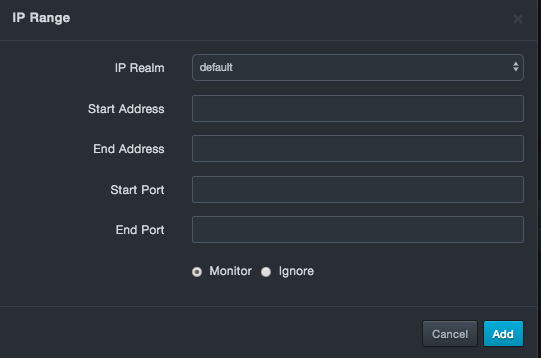
-
Complete the fields.
-
Click Add.
-
At the top-right side of the page, click Commit.
After you add or commit your settings, you can edit or delete the settings.
Fields in the IP Range Dialog Box
| Field | Description | Default |
|---|---|---|
| IP Realm | Select an IP realm. | default |
| Start Address | IP address at the start of the address range. | — |
| End Address | IP address at the end of the address range. | — |
| Start Port | Number of the port at the start of the port range. | — |
| End Port | Number of the port at the end of the port range. | — |
| Monitor/Ignore | Select whether the platform will monitor or ignore the specified IP address and port ranges. Choices are:
|
Monitor |
Editing Capture Filter Settings in Basic Mode
There might be times when you want to edit the capture filter settings. For example, you might want to change the starting or ending IP address or port number.
To edit capture filter settings in basic mode
-
Click Settings > Advanced.
-
In the left pane, click Capture Filters. The Capture Filters page appears.
-
At the top-left side of the page, confirm that the Basic button is selected.
-
On the right side of the page, click the
 icon that corresponds to the capture filter settings you want to
edit. The IP Range dialog box appears.
icon that corresponds to the capture filter settings you want to
edit. The IP Range dialog box appears. -
Change the settings as desired.
-
Click Save.
-
At the top-right side of the page, click Commit.
Deleting Capture Filter Settings in Basic Mode
If you no longer need capture filter settings, you can delete them.
To delete capture filter settings in basic mode
-
Click Settings > Advanced.
-
In the left pane, click Capture Filters. The Capture Filters page appears.
-
At the top-left side of the page, confirm that the Basic button is selected.
-
On the right side of the page, click the
icon that corresponds to the capture filter settings you want to delete.
Using Advanced Mode to Configure Capture Filters
If you prefer to configure capture filters using the BPF filtering syntax, use advanced mode to specify these settings. Advanced mode allows you to configure capture filters with more granularity than basic mode.
To configure capture filters using advanced mode
-
Click Settings > Advanced.
-
In the left pane, click Capture Filters. The Capture Filters page appears.
-
At the top-left side of the page, click the Advanced button.
-
When the caution message appears, click Switch. A page similar to the following appears. Each capture port (R4/1, R4/2, and so on) has a BPF field into which you can enter the capture filter settings for that port.
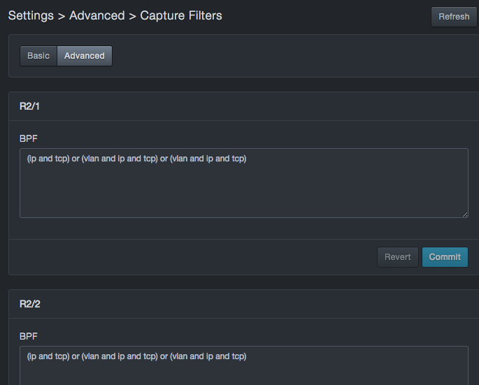
In the BPF, enter the IP, TCP, and VLAN settings for the appropriate capture port.
-
At the bottom-right side, click Commit to apply your settings to the port (or click Revert to discard them and revert to the previous settings). If the syntax is correct, the message Save appears briefly. If the syntax is incorrect, an error message appears; click OK to clear the message, and then correct the syntax.
After you specify the capture port settings, you can edit them as necessary by repeating this procedure.
Syslog
Path: Settings > Advanced > Syslog
Using the Syslog page, you can configure syslog settings.
| | Note: The default size of the syslog is 8K. Logs that exceed this size are truncated automatically. If you expect syslog messages greater than 8K, increase the default message size to avoid truncation. |
The platform collects and reports health records and event messages to a local syslog server. The platform then sends health messages every 10 minutes and sends an event record every time an event is created.
To configure syslog reporting
-
Click Settings > Advanced.
-
In the left pane, click Syslog. The Syslog page appears.
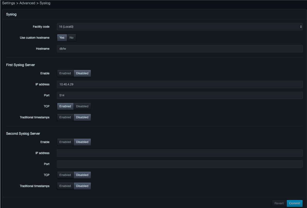
-
Complete the fields
-
Click Commit.
Fields in the Syslog Page
| Field | Description | Default |
|---|---|---|
| Enable | Enables or disables syslog reporting. | Disabled |
| IP address | IP address of the syslog server. | — |
| Port | Port number of the syslog server. | 514 |
| Facility code | Facility code used to specify the type of program that is logging the message. Messages with different facilities may be handled differently. The list of facilities available is defined by RFC 3164. For more information, refer to https://en.wikipedia.org/wiki/Syslog. | 16(Local0) |
| TCP | Enables or disables TCP transmissions to the syslog server. | Disabled |
| Traditional timestamps | Enables or disables traditional timestamps. | Disabled |
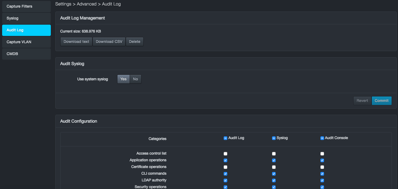
Audit Log
Path: Settings > Advanced > Audit Log
The platform maintains an audit log that records events associated with it. Using the Audit Log page, you can export the audit log in text or comma-separated-value (CSV) format. You can also turn the audit log on or off and select the categories that appear in the audit log.
The following figures show examples of audit log entries:
2017-09-28T17:30:31-05:00 [sysOps] auditCode=2039 auditMessage="User accepted the EULA" userId=admin sessionId=Korm_AhSPgyNuzPA4u7W2FnPPl205cL_ src=10.40.7.216 target="EULA:eulaRequired" oldValue="true" newValue="false"
2017-09-28T17:30:31-05:00 [secOps] auditCode=1024 auditMessage="Create session" userId=admin sessionId=yoi0OlKAjgiv5HWj8QgfLPa0QmZPJvy0 src=10.40.7.216 target="Session" oldValue="null" newValue="yoi0OlKAjgiv5HWj8QgfLPa0QmZPJvy0"
2017-09-28T17:30:31-05:00 [secOps] auditCode=1009 auditMessage="User login succeeded" userId=admin sessionId=yoi0OlKAjgiv5HWj8QgfLPa0QmZPJvy0 src=10.40.7.216 target="User:admin" cookies="[{"name":"dbnetworks"}]"
2017-09-28T17:34:52-05:00 [secOps] auditCode=1000 auditMessage="Create user" userId=system sessionId=null src=LocalAuthStore:addUser cfg="{"username":"cmdb","password":"REDACTED","capabilities":["Admin","__api"],"displayName":"","sessionTimeout":60,"overridePolicy":false,"remoteStore":null,"altIdent":null, "accountExpiration":0}"
2017-09-28T17:34:52-05:00 [secOps] auditCode=1028 auditMessage="Create API key" userId=admin sessionId=yoi0OlKAjgiv5HWj8QgfLPa0QmZPJvy0 src=10.40.7.216 target="APIKey:cmdb:keyID" newValue="cmdb"
Exporting the Audit Log
To export the audit log
-
Click Settings > Advanced.
-
In the left pane, click Audit Log. The Audit Log page appears under Audit Log Management. Current size shows the size of the audit log.
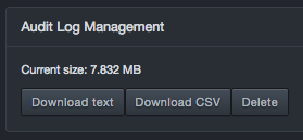
-
Below the Current size field, click Download text or Download CSV.
Deleting the Audit Log
To delete the audit log
-
Click Settings > Advanced.
-
In the left pane, click Audit Log. The Audit Log page appears.
-
Under Audit Log Management, click Delete.
-
When a message asks you to confirm the deletion of the entire audit history, click Delete (or click Cancel to retain the audit history).
Redirecting Audit Syslog Output
Using the Audit Syslog area in the Audit Log page, you can change the location where the audit syslog is output.
To redirect the audit syslog output
-
Click Settings > Advanced.
-
In the left pane, click Audit Log. The Audit Log page appears.
-
Under Audit Syslog, next to Use System Syslog, click No.
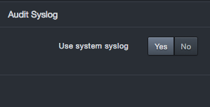
Fields appear for entering the IP address and port number where the system will send the audit syslog.
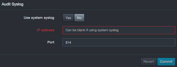
-
Complete the fields.
-
Click Commit.
Fields in the Audit Syslog Area
| This Permission… | Allows Users to… |
|---|---|
| IP address | IP address of the destination where the audit syslog should be sent. If the destination is the system syslog, you can leave this field blank. |
| Port | Number of the port for the destination where the audit syslog should be sent. |
Showing or Hiding Audit Categories
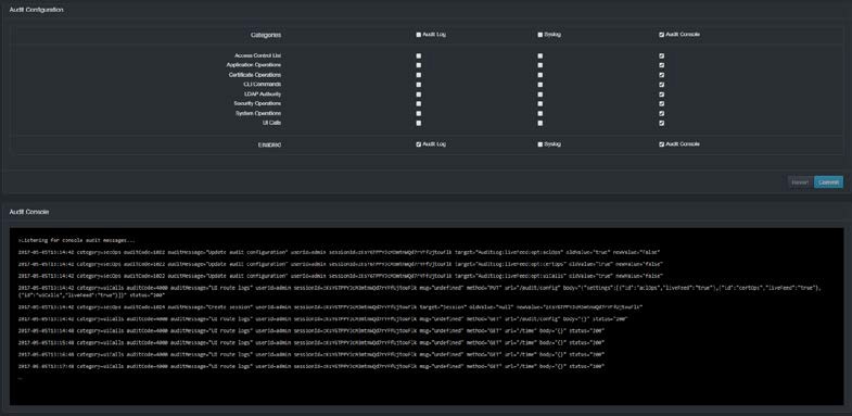
The Audit Configuration area in the Audit Log page allows you to select the categories you want shown in the audit log, syslog, and audit console. You can also enable or disable these functions.
To show or hide audit categories
-
Click Settings > Advanced.
-
In the left pane, click Logging. The Audit Log page appears. The Audit Configuration area shows the categories on the left side and columns for the audit log, syslog, and audit console.
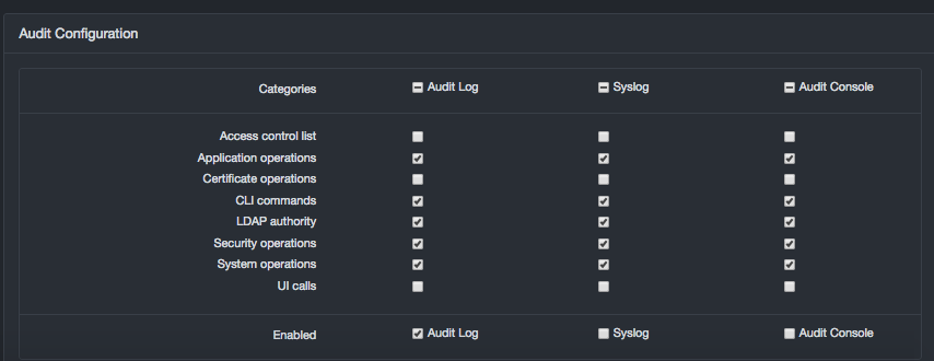
-
Under Audit Configuration, check the categories you want to show in the audit log, syslog, and audit console. Uncheck the ones you want to hide.
-
On the Enabled row, check the facilities you want to enable and uncheck the ones you want to disable:
-
Audit Log writes the logs to a file on the local system. When an audit log is generated with this option selected, the log information is downloaded from the local audit log.
-
Syslog forwards audit log entries to the syslog server you have set up.
-
Audit Console displays a live audit console similar to the following at the bottom of the page for viewing audit log entries in real time. You must click Commit to display the console.
-
-
Click Commit.
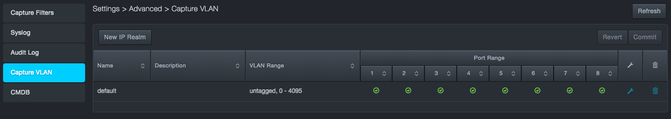
Capture VLAN
Path: Settings > Advanced > Capture VLAN
Using the Configure VLAN page, you define the realms. A realm is a context in which an IP address is interpreted throughout the platform. You can configure realms based on physical capture port numbers, VLAN tags, or both. Initially, all ports and all VLAN tags go into the “default” realm.
If traffic on a test VLAN uses the same IP addresses as traffic on a production network, you can use the VLAN tags to place the traffic into distinct realms, so that the same IP address is treated as two different entities. Each received packet is put into a realm, starting at the top of the list and working down until a match is made.
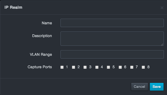
Adding a New Realm
An IP realm definition consists of:
-
Realm Name
-
Realm Description
-
VLAN Range
-
Capture ports on which the traffic is expected to appear
To add a new realm
-
Click Settings > Advanced.
-
In the left pane, click Capture VLAN. The Capture VLAN page appears.
-
At the top-left side of the page, click New IP Realm. The IP Realm dialog box appears.
-
Complete the fields.
-
Click Save.
Fields in the IP Realm Dialog Box
| Field | Description | Default |
|---|---|---|
| Name | Enter a name for this realm. The name should allow you to differentiate this realm from others you might have added. | — |
| Description | Enter a description for this realm. | — |
| VLAN Range | Specify the range of VLANs that this realm will cover. | — |
| Capture Ports | Check the capture ports that this realm will cover. | — |
Editing Realms
There might be times when you want to edit a realm. For example, you might want to change the name, description, VLAN ports, or capture ports for a realm.
To edit a realm
-
Click Settings > Advanced.
-
In the left pane, click Capture VLAN. The Capture VLAN page appears.
-
On the right side of the page, click the
icon that corresponds to the realm you want to edit. The IP Range dialog box appears. -
Change the settings as desired.
-
Click Save.
Deleting Realms
If you no longer need a realm, you can delete it from the system.
To delete a realm
-
Click Settings > Advanced.
-
In the left pane, click Capture VLAN. The Capture VLAN page appears.
-
On the right side of the page, click the
icon that corresponds to the realm you want to delete.
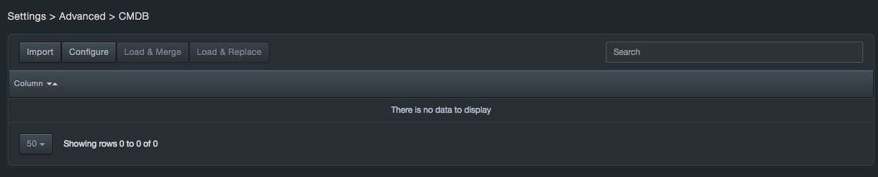
CMDB
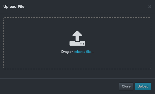
Path: Settings > Advanced > CMDB
The CMDB function allows users to add fields and data to the service discovery and service activity screens to integrate Configuration Management Database (CMDB) information into the Visibility tables of the platform.
The high level process for adding asset information is:
-
Download service discovery data to your local machine
-
Update the data with on offline editor.
-
Import and process the data.
-
View the data on the service discovery page.
CMDB Update Flow
To update CMDB Data
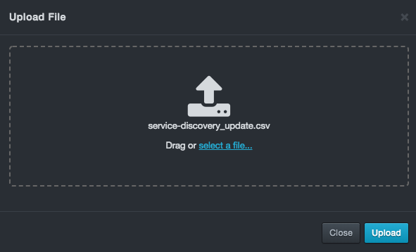
-
Update a service discovery CSV with new fields and data
-
Import the data
-
Select the Configure option
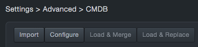
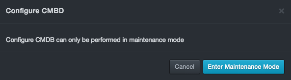
-
The system will restart and enter Maintenance Mode.
-
Log in to the system.
-
Go to Settings > Advanced > CMDB
-
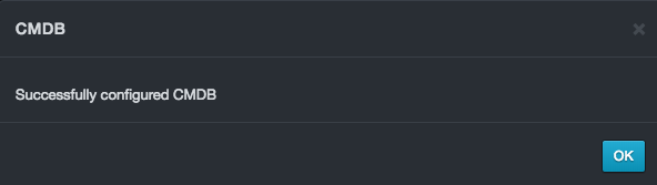
Select the Configure button. A status message will be displayed:
-
Go to System > Enter Production Mode and reboot the system back to production mode.
-
The system should reboot and return to the CMDB page.
-
Select the Load & Merge button. A status message will be displayed similar to above.
-
The system will display the added columns:
-
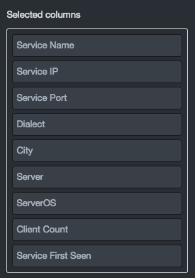
Go the Visibility > Services page, click the gear
 button, and Configure columns.
 -
Move the added columns to the Selected columns field:
-
View the data:

Contact Technical Support
For any technical difficulties you may experience, you can contact DB CyberTech Technical Support at the following:
Email: support@dbcybertech.com
Phone: 1(800) 375-0592
Appendix A Glossary
| Term | Definition |
|---|---|
| API | Application Programming Interface. A set of routines, protocols, and tools for building software applications. |
| Blacklisted statements | Statements that are not added to the learned set. Typically, these statements are used to filter out benign statements generated by DBAs or other non-application related interactions |
| BPF | Berkeley Packet Filter. An architecture for user-level packet capture. BPF provides a raw interface to data link layers in a protocol-independent fashion. |
| CAC | A "smart" card about the size of a credit card used as identification for active duty uniformed service personnel, Selected Reserve, DoD civilian employees, and eligible contractor personnel. |
| CSV | Comma-separated value. Data format where each piece of data is separated by a comma |
| DHCP | Dynamic Host Protocol Configuration. A standardized network protocol used on Internet Protocol networks to dynamically distribute network configuration parameters, such as IP addresses, for interfaces and services. With DHCP, computing devices like the platform request IP addresses and networking parameters automatically from a DHCP server, reducing the need to configure these settings manually. |
| DNS | Domain Name System. A hierarchical decentralized naming system for computers, services, or any resource connected to the Internet or a private network. DNS translates domain names into the numerical IP addresses to locate and identify computer services and devices with the underlying network protocols. |
| LDAP | Lightweight Directory Access Protocol. A protocol for accessing a directory listing in a TCP/IP network. It is a sibling protocol to HTTP and FTP and uses the ldap:// prefix in its URL. |
| Learned set | Contains statements considered to be part of the application’s normal behavior. |
| MAC | Media Access Control. A hardware address that uniquely identifies each node of a network. |
| MTU | Maximum Transmission Unit. The largest physical packet size measured in bytes that a network can transmit. Any messages larger than the MTU are divided into smaller packets before being sent. |
| Network File System | A client/server application that allows network users to access shared files stored on computers of different types using a Virtual File System that runs on top of TCP/IP. |
| NTP | Network Time Protocol. A networking protocol for clock synchronization between computer systems over packet-switched, variable-latency data networks. |
| pcap | Short for packet capture. A program for capturing network traffic. |
| Server Message Block | A message format used by Windows to share files, directories, and devices. |
| SSL | Secure Sockets Layer. A protocol for transmitting private documents via the Internet. SSL uses a cryptographic system that uses two keys to encrypt data. |

DB CyberTech
15015 Avenue of Science
Suite 150
San Diego, CA 92128
http://www.dbcybertech.com